433MHz 범용 무선 스위치, Model : KR2201E 설명/설명서
-

- 2025.02.10 - 22:43 2025.02.07 - 14:46 3014 9
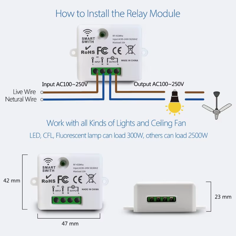
433Mhz 범용 무선 스위치 스마트 Lmap/LED/조명 컨트롤러 디젤 AC85V ~ 265V RF 릴레이 수신기 보드 및 벽 스위치
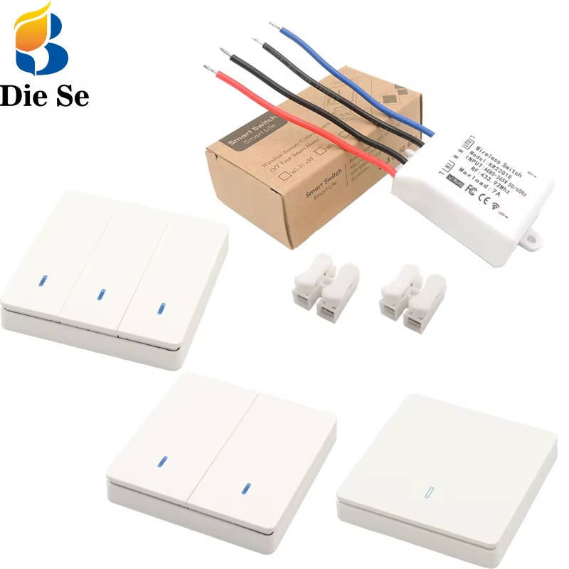
ㄴ 벽 스위치 / 와이어 커넥터 / 무선 수신기 (본체)
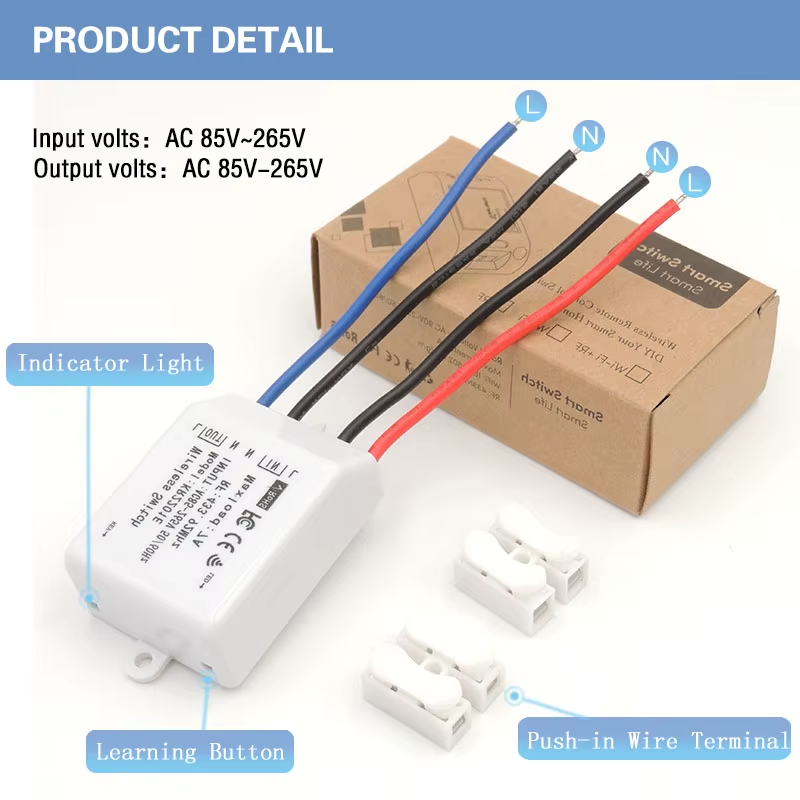
Wireless Switch
Model : KR2210E
Input : AC85~265V 50/60Hz
RF : 433.92 MHz
Max load : 7A (실제 제품엔 10A로 표기)
Code : 1527 learning code or 2262 fixed code
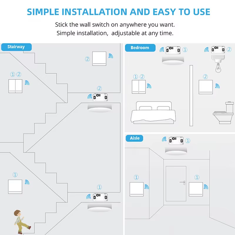
ㄴ 본체 1개 = 벽스위치 1개에 on/off 교대 작동 연결 가능
ㄴ 본체 1개 = 벽스위치 여러개를 각각 on / off 전용으로 연결 가능
ㄴ 본체 여러개 = 벽스위치 1개로 동시 on/off 작동 연결 가능
알리 제품 링크 : https://www.aliprice.com/s?id=4000969984397_18&u=&c=3g4ccTVflRJ1W7TqFB0HKHWBHW
-
25
댓글9
-
세상의모든계산기
설명서 (영문)
User manual
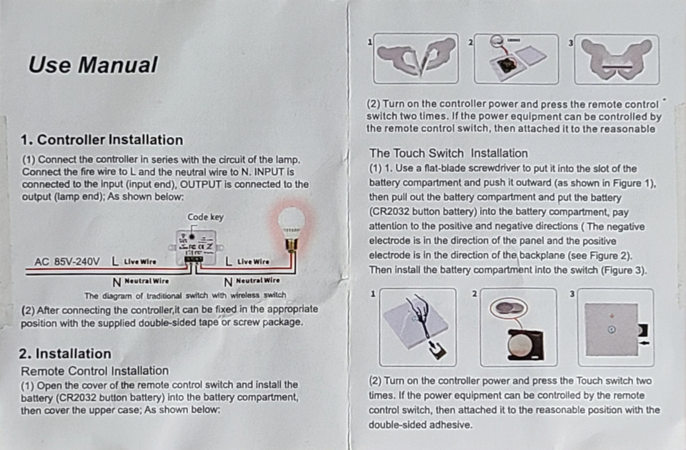
1. controller installation
(1) Connect the controller inseries with the circuit of the lamp. Connect the fire wire to L and the neutral wire to N. INPUT is connected to the input (input end), OUTPUT is connected to the output(lamp end); As shown below:
(2) After connecing the controller it can be fixed in the appropriate position with the supplied double-sided tape or screw package.
2. Installtion
Remote Control Installation
(1) Open the cover of the remote control switch and install the battery(CR2032 Button battery) into the battery compartment, then cover the upper case; As shown below:
(2) Turn on the controller power and press the remote control switch two times. If the power equipment can be controlled by the remote control switch, then attatch it to the reasonable
The Touch Switch Installation
(1) 1. Use a flat-balde screwdriver to put it into the slot of the battery compartment and push it outward (as shown in Figure 1), then pull out the battery compartment and put the battery(CR2032 button battery) into the battery compartment, pay attention to the position and negative directions (The negative electrode is in the direction of the panel and the positive electrode is inthe direction of the backplane (see Figure 2). Then install the battery compartment into the switch (Figure 3).
(2) Turn on the controller power and press the Touch switch two times. If the power equipment can be controlled by remote control switch, then attatch it to the reasonable position with the double-sided adheive.
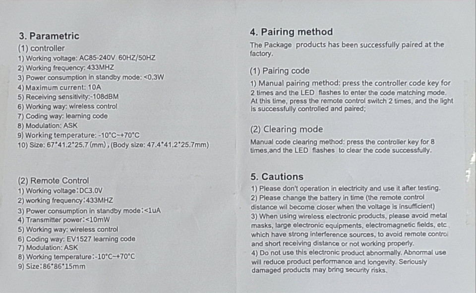
3. Parametic
(1) controller
1) Working voltage: AC85~240V, 60Hz/50Hz
2) Working frequency: 433MHz
3) Power consumption in standby mode: <0.3W
4) Maximum current: 10A
5) Receiving sensitivity:-108dBM
6) Working way: wireless control
7) Coding way: learning code
8) Modulation: ASK
9) Working temperature: -10℃ ~ +70℃
10) Size: 67*41.2*25.7mm (Body size: 47.4*41.2*25.7mm)
(2) Remote Control
1) Working voltage: DC3.0V
2) working frequency: 433MHz
3) Power consumption in standby mode:<1㎼
4) Transmitter power:<10㎽
5) Working way: wireless control
6) Coding way: EV1527 learning code
7) Modulation: ASK
8) Working temperature: -10℃ ~ +70℃
9) Size: 86*86*15mm
4. Pairing method
The Package products has been sucessfully paired at the factory.
(1) Pairing code
1) Manual pairing method: press the controller code key for 2 times and the LED flashes to enter code matching mode.
At this time, press the remote control switch 2 times, and the light is successfully controlled and paired.
(2) Cleaning mode
Manual code clearing method: press the controller key for 8 times, and the LED flashes to clear the code successfully.
5. Caution
1) Please don't operation in electricity and use it after testing.
2) Please change the battery in time (the remote control distance will become closer when the voltage is insufficient)
3) When using wireless electonic products, please avoid metal masks, large elecronic equipments, electromagnetic fields, etc which have strong inference sources, to avoid remote control and short receiving distance or not working properly.
4) Do not use this elecronic product abnormally. Abnormal use will reduce product performance and longevity. Seriously damaged products may bring securty risks. -
세상의모든계산기
페어링 방법 상세 설명
1. 공장에서 나올 때 여러 작동 모드 중 무작위로 설정될 수 있습니다.여러 테스트를 거치기 때문에 그렇다고 합니다. 초기화 후 사용하세요.
2. 초기화
적당한 물건으로 수신기의 Key 구멍 안의 버튼을 8번 연속해 누르면
-> LED가 5~6번? 빠르게 점멸하고
-> 등록된 벽 스위치(목록)가 리셋됨.주의) Key 구멍은 상단에 있을 수도 있고, 옆구리에 있을 수도 있습니다.
주의) 힘을 주어 누를 필요는 없습니다.
쉽게 눌리며 오히려 너무 힘을 주면 부품 파손 위험이 있습니다.딸깍하는 소리는 없지만, 그런 느낌은 손끝으로 받을 수 있습니다.
주의) 적당한 물건 = 이쑤시개(뾰족한 부분을 끊어 버리고, 뭉툭하게 만드는 편이 좋음)
= 머리가 그렇게 크지 않은 드라이버
3. 페어링 (토글 모드 기준 설명)
Key를 2번 누르면 (토글) 페어링 모드로 진입함
-> (2~3초 대기하면) LED 가 켜진 채 유지됨.
-> 벽 스위치를 1번 누르고 2~3초 대기.
-> LED 2~3회 깜빡이고 꺼짐 = 페어링 모드 종료됨.
4. 추가 페어링
위 3. 과정을 통해 이미 페어링된 상태에서, 위 3과정을 반복하면 됨.
주의) 판매 페이지에는 20개까지 저장된다고 나옵니다.
주의) 3가지 모드는 조합하여(섞여서) 등록될 수 있습니다.
-
세상의모든계산기
작동 모드 (페어링 종류)
3 가지 모드에서 송신기를 릴레이 수신기 모듈과 일치시킬 수 있습니다.
순간 모드:
1. 버튼을 누르는 동안 -> 릴레이가 켜집니다.
2. 버튼에서 손을 떼면 -> 릴레이가 꺼집니다.토글 모드:
1. (릴레이가 꺼진 상태에서) 버튼을 누르면 -> 릴레이가 켜집니다.
2. (릴레이가 켜진 상태에서) 버튼을 누르면 -> 릴레이가 꺼집니다.래치 모드:
1. 버튼 "A" 를 누르면 -> 릴레이가 항상 켜집니다.
2. 버튼 "B" 를 누르면 -> 릴레이가 항상 꺼집니다. -
세상의모든계산기
순간 모드 설정
1. (수신기에서) 학습 버튼을 1회 누릅니다. 3 초 동안 기다리십시오.
2. 리모컨의 버튼 하나를 누릅니다. 3 초 동안 기다리십시오. 페어링 종료.
토글 모드 설정
1. (수신기에서) 학습 버튼을 2회 연속 누릅니다. 3 초 동안 기다리십시오.
2. 리모컨의 버튼 하나를 누릅니다. 3 초 동안 기다리십시오. 페어링 종료.
래치 모드 설정
1. (수신기에서) 학습 버튼을 3회 연속 누릅니다. 3 초 동안 기다리십시오.
2. "A" 버튼(On)을 누릅니다. 3 초 동안 기다리십시오.
3. "B" 버튼(Off)을 누릅니다. 3 초 동안 기다리십시오. 페어링 종료. -
세상의모든계산기2025.02.07 - 18:06 #53979Q & A
Q: 하나의 수신기를 다른 벽 스위치로 제어 할 수 있습니까?
A: 예, 각 수신기는 약 25 개의 벽 스위치를 추가 할 수 있습니다.
Q: 하나의 벽 스위치가 2 수신기를 개별적으로 제어 할 수 있습니까?
A: 예, 2 개의 버튼이있는 벽 스위치는 2 개의 수신기를 제어 할 수 있으며 3 개의 버튼이있는 벽 스위치는 3 개의 수신기를 제어 할 수 있습니다.
Q: 벽면 스위치의 1 버튼이 2 수신기를 동시에 제어 할 수 있습니까?
A: 네, 직접 프로그래밍할 수 있습니다. 예를 들어 버튼 "1" 과 수신기 "1" 을 일치시킨 다음 버튼 "1" 과 수신기 "2" 도 일치시킵니다. 이 버튼 "1" 은 수신기 "1" 과 수신기 "2" 를 동시에 제어 할 수 있습니다. -
세상의모든계산기
위 제품은 페어링 방식이 약간 다르네요.
Key를
ㄴ 3초 동안 누르고 있다가 손을 떼고 (LED on) 페어링 : On/Off 모두 연동 = 토글 모드
ㄴ 5초 동안 누르고 있다가 손을 떼고 (LED 빠르게 깜빡) 페어링 : On 만 연능 = 래치 모드
ㄴ 7초 동안 누르고 있다가 손을 떼고 (LED 느리게 깜빡) 페어링 : Off 만 연동 = 래치 모드
ㄴ 9초 동안 누르고 있다가 손을 뗌 (LED off) : 등록된 버튼 목록 리셋
* Key 를 n회 누르는 것은 페어링 기능으로 작동하지 않고, on/off 기능이 즉시 작동합니다.
* 순간 모드 기능은 없습니다.

세상의모든계산기 님의 최근 댓글
아 그렇네요. 감사합니다. ^^ 2026 04.28 정적분 구간에 미지수가 있고, solve 를 사용할 수 없을 때 그 값을 확인하려면? https://allcalc.org/57087 `SOLVE` 기능 내에 `∫(적분)` 기호를 사용할 수 없을 때 뉴튼-랩슨법을 직접 사용하는 방법 2026 04.15 뉴턴-랩슨 적분 방정식 시각화 v1.0 body { font-family: 'Pretendard', -apple-system, BlinkMacSystemFont, "Segoe UI", Roboto, Helvetica, Arial, sans-serif; display: flex; flex-direction: column; align-items: center; background: #f8f9fa; padding: 40px 20px; margin: 0; color: #333; } .container { background: white; padding: 40px; border-radius: 20px; box-shadow: 0 15px 35px rgba(0,0,0,0.08); max-width: 900px; width: 100%; } header { border-bottom: 2px solid #f1f3f4; margin-bottom: 30px; padding-bottom: 20px; } h1 { color: #1a73e8; margin: 0 0 10px 0; font-size: 1.8em; } p.subtitle { color: #5f6368; margin: 0; font-size: 1.1em; } .equation-box { background: #f1f3f4; padding: 15px; border-radius: 10px; text-align: center; margin-bottom: 30px; font-size: 1.3em; } canvas { border: 1px solid #e0e0e0; border-radius: 12px; background: #fff; width: 100%; height: auto; display: block; } .controls { margin-top: 30px; display: flex; gap: 15px; align-items: center; justify-content: center; flex-wrap: wrap; } button { padding: 12px 25px; border: none; border-radius: 8px; background: #1a73e8; color: white; cursor: pointer; font-weight: 600; font-size: 1em; transition: all 0.2s; box-shadow: 0 2px 5px rgba(26,115,232,0.3); } button:hover { background: #1557b0; transform: translateY(-1px); box-shadow: 0 4px 8px rgba(26,115,232,0.4); } button:active { transform: translateY(0); } button.secondary { background: #5f6368; box-shadow: 0 2px 5px rgba(0,0,0,0.2); } button.secondary:hover { background: #4a4e52; } .status-badge { background: #e8f0fe; color: #1967d2; padding: 8px 15px; border-radius: 20px; font-weight: bold; font-size: 0.9em; } .explanation { margin-top: 40px; padding: 25px; background: #fff8e1; border-left: 5px solid #ffc107; border-radius: 8px; line-height: 1.8; } .explanation h3 { margin-top: 0; color: #856404; } .math-symbol { font-family: 'Times New Roman', serif; font-style: italic; font-weight: bold; color: #d93025; } .code-snippet { background: #202124; color: #e8eaed; padding: 2px 6px; border-radius: 4px; font-family: monospace; } 📊 Newton-Raphson 적분 방정식 시뮬레이터 미분적분학의 기본 정리(FTC)를 이용한 수치해석 시각화 목표 방정식: ∫₀ᴬ (2√x) dx = 20 을 만족하는 A를 찾아라! 계산 시작 (A 추적) 초기화 현재 반복: 0회 💡 시각적 동작 원리 (Newton-Raphson & FTC) Step 1 (오차 측정): 현재 A까지 쌓인 파란색 면적이 목표치(20)와 얼마나 차이나는지 계산합니다. Step 2 (FTC의 마법): 면적의 변화율(미분)은 그 지점의 그래프 높이 f(A)와 같습니다. Step 3 (보정): 다음 A = 현재 A - (면적 오차 / 현재 높이) 공식을 사용하여 A를 이동시킵니다. 결론: 오차를 현재 높이로 나누면, 오차를 메우기 위해 필요한 가로 길이(ΔA)가 나옵니다. 이 과정을 반복하면 정답에 도달합니다! const canvas = document.getElementById('graphCanvas'); const ctx = canvas.getContext('2d'); const iterText = document.getElementById('iterText'); // 수학 설정 const targetArea = 20; const f = (x) => Math.sqrt(x) * 2; // 피적분 함수 f(x) = 2√x const F = (x) => (4/3) * Math.pow(x, 1.5); // 정적분 결과 F(x) = ∫ 2√x dx = 4/3 * x^(3/2) let A = 1.5; // 초기값 let iteration = 0; let animating = false; // 그래프 드로잉 설정 const scale = 50; const offsetX = 60; const offsetY = 380; function drawGrid() { ctx.strokeStyle = '#f1f3f4'; ctx.lineWidth = 1; ctx.beginPath(); for(let i=0; i 2026 04.11 참값 : A = ±2√5 근사값 : A≈±4.472135954999579392818347 2026 04.10 fx-570 ES 입력 결과 초기값 입력 반복 수식 입력 반복 결과 2026 04.10